Unlock a world of possibilities! Login now and discover the exclusive benefits awaiting you.
- Qlik Community
- :
- Support
- :
- Support
- :
- Knowledge
- :
- Member Articles
- :
- Configuring BIG-IP LTM VE for Qlik Sense Load Bala...
- Move Document
- Delete Document
- Subscribe to RSS Feed
- Mark as New
- Mark as Read
- Bookmark
- Subscribe
- Printer Friendly Page
- Report Inappropriate Content
Configuring BIG-IP LTM VE for Qlik Sense Load Balanced Cluster
- Move Document
- Delete Document
- Mark as New
- Bookmark
- Subscribe
- Mute
- Subscribe to RSS Feed
- Permalink
- Report Inappropriate Content
Configuring BIG-IP LTM VE for Qlik Sense Load Balanced Cluster
Jan 14, 2016 12:38:05 AM
Jan 14, 2016 12:38:05 AM
Introduction
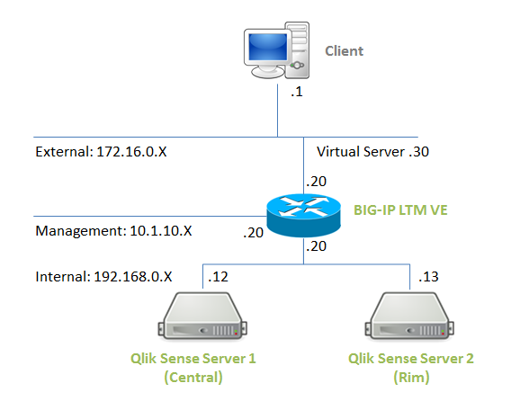
F5 BIG-IP is one of the market leading load balancer which can be used for load balancing/clustering Qlik products. F5 provides a virtual machine image of BIG-IP Local Traffic Manager(LTM) build on the top of CentOS and available for trial. With this virtual machine image, you can test the configuration of BIG-IP LTM features on a VM or cloud environment without setting up BIG-IP hardware products. In an attempt to test the configuration of BIG-IP needed for Qlik Sense to work, I have set up Qlik Sense 2 nodes cluster with BIG-IP LTM VE placed in front on VMWare vSphere ESXi demo environment.
This article explains the basic configuration of BIG-IP LTM VE needed for Qlik Sense load balanced clustering.
Deploying BIG-IP LTM VE on VMWare ESXi
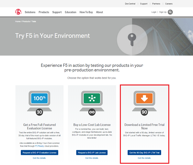
BIG-IP LTM VE Trial Download
The virtual machine images are provided in the formats of VMWare ESXi, vCloud, Citrix Xen Server and KVM. (VMWare ESXi is used in this demo.) The virtual image and registration key of BIG-IP LTM Trial can be obtained from the following site :
https://f5.com/products/trials/product-trials
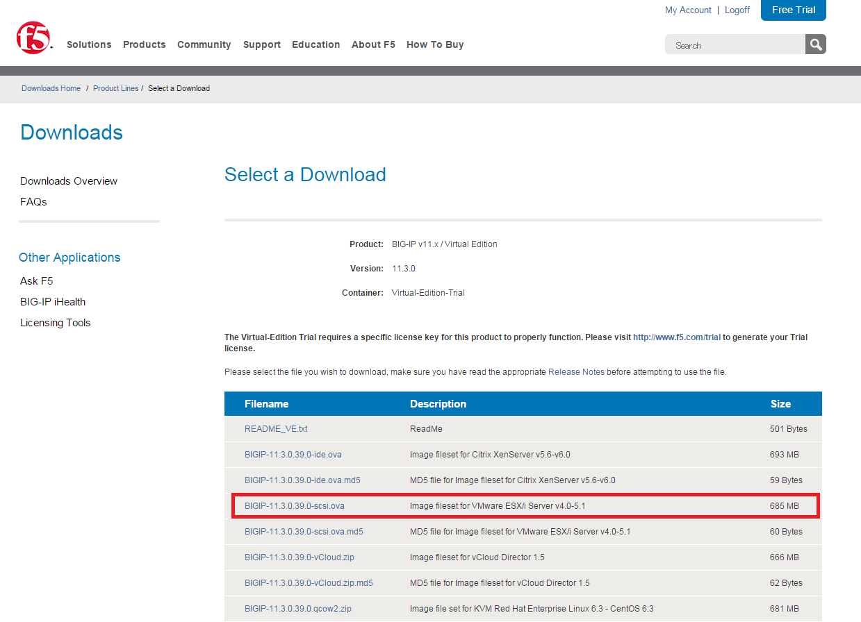
Download BIGIP-xx.x.x.xx.x-scsi.ova for VMWare ESXi.
Deploying virtual machine image to VMWare ESXi
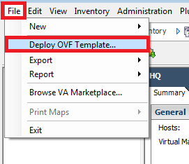
The VMWare virtual machine image is stored in QVF template format. To deploy the downloaded image to VMWare ESXi, click "File" > "Deploy OVF Template" on vSphere Client, select the downloaded BIGIP-xx.x.x.xx.x-scsi.ova file, and follow the instruction.
In the deployment process, please make sure that the network adopters are associated with appropriate networks. 4 network adopters are defined as default in the BIG-IP LTE VE image, and in this demo, they are linked with networks in the following way:
| Adapter | Network |
|---|---|
| Network adopter 1 | Management Network |
| Network adopter 2 | Internal Network |
| Network adopter 3 | External Network |
| Network adopter 4 | (not used) |
Management IP address Assignment
Connect to the console and login with the following user/password:
- username: root
- password: default
(When the startup program of BIG-IP OS stuck at "GRUB Loading stage2" on the virtual machine console, add a serial port on the virtual machine settings.)
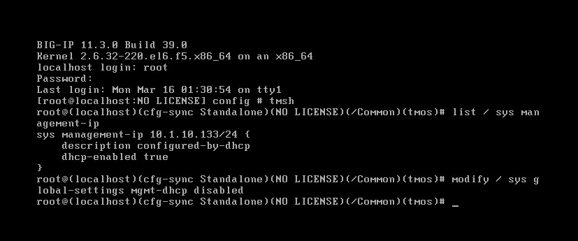
tmsh
modify / sys global-settings mgmt-dhcp disabled
create / sys management-ip 10.1.10.20/255.255.255.0 //Enter management ip address/subnet mask
create / sys management-route default gateway 10.1.10.1 //Enter default gateway address
save / sys config
Applying license
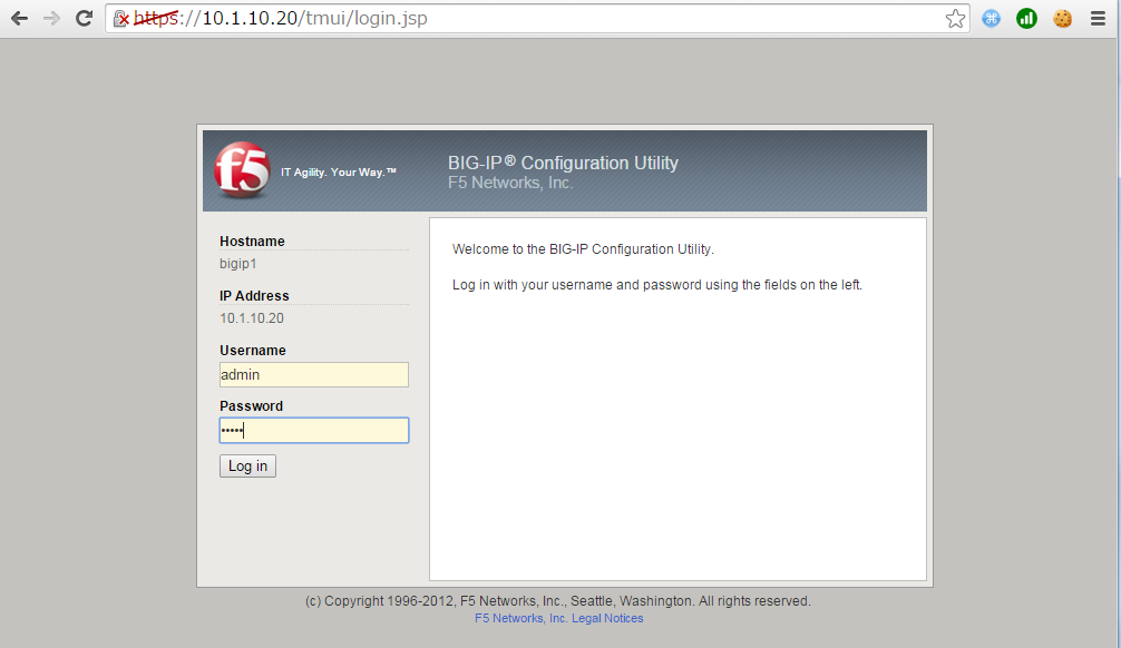
Access to the following URL on a browser:
- https://<management ip address>
Login with the following user/password:
- username: admin
- password: admin
On "Setup Utility", click "next", enter a registration key and enter "next".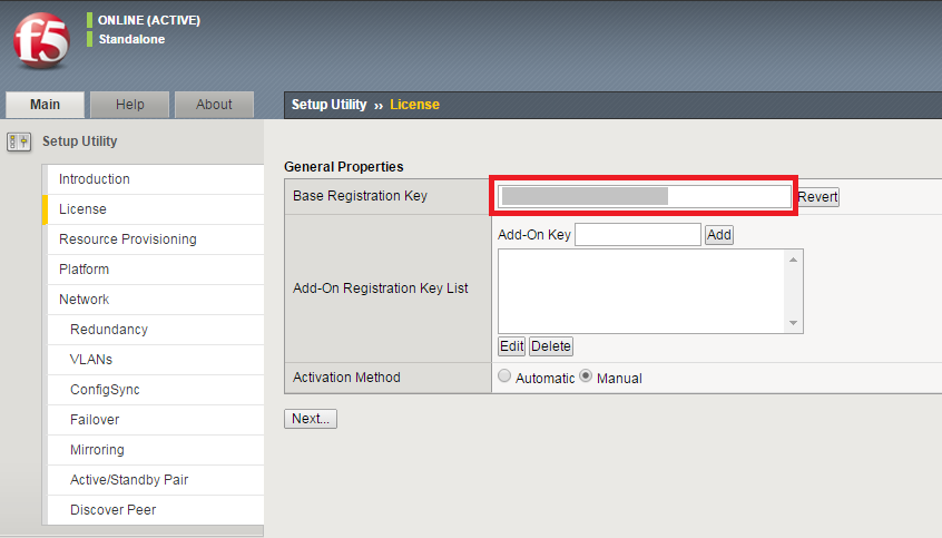
Enter license key to activate the license. (License key can be obtained by supplying your product dossier on the following license server site.)
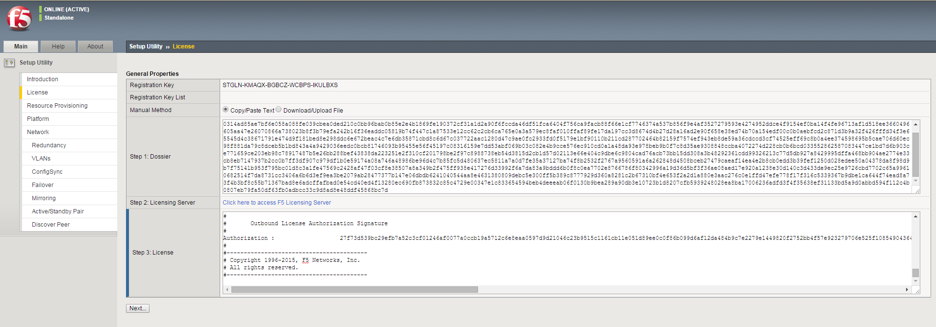
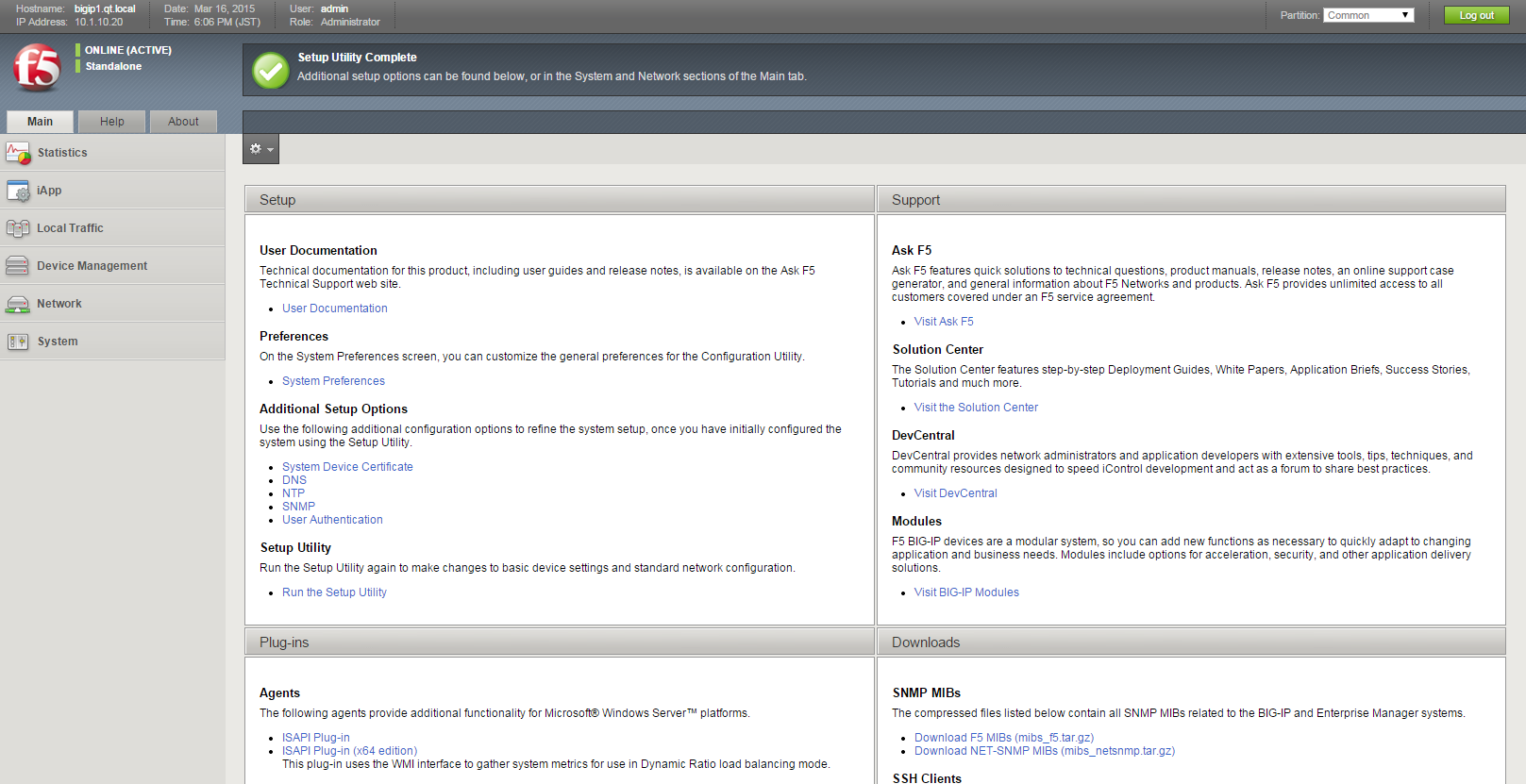
Follow the instruction and complete "Setup Utility".
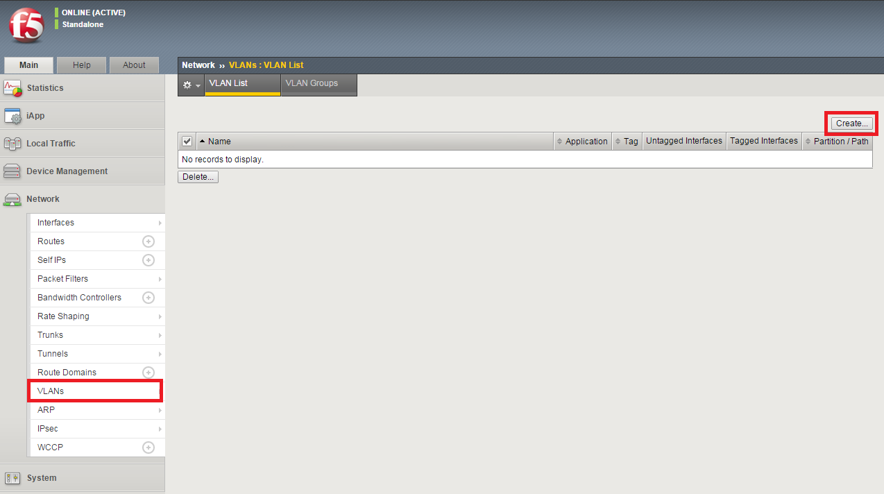
Creating VLANs
A VLAN is a logical grouping of interfaces connected to network devices. In this demo, two VLANs (external and internal) are created.
Select "Network" > "VLANs", and click "Create" button.
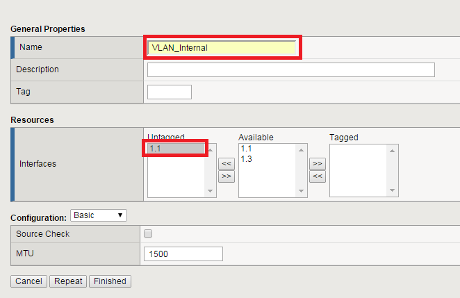
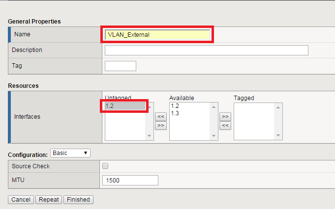
Create VLAN for internal network (VLAN_Internal).
Create VLAN for external network (VLAN_External).
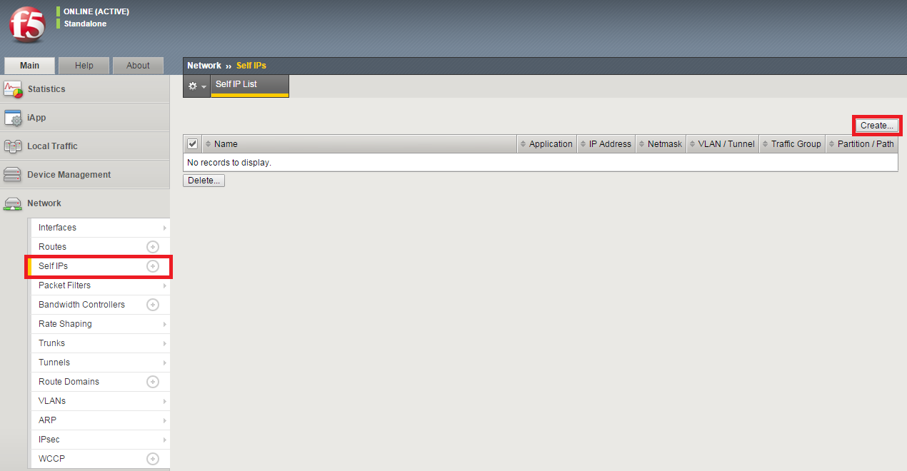
Creating Self IPs for VLANs
Self IP addresses are assigned to VLANS, and you can access to BIG-IP LTM device using the IPs in VLANs.
Select "Network" > "Self IPs", and click "Create" button.
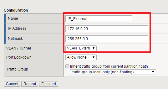
Create a Self IP for VLAN_External.
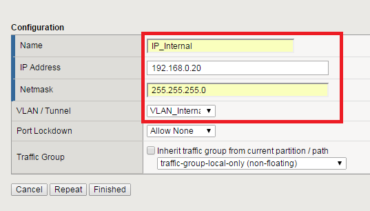
Create a Self IP for VLAN_Internal.
Ping to the IP addresses and make sure that you can connect to the BIG-IP LTM using the IPs.
Qlik Sense Setup
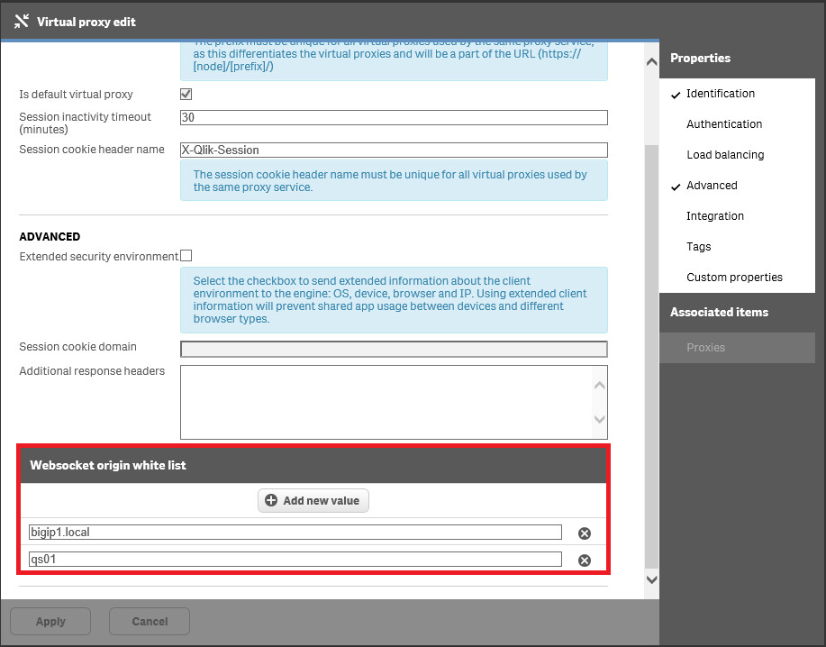
Adding entries to Websocket origin white list
On Qlik Sense QMC, nagivate to "CONFIGURE SYSTEM">"Virtual proxies" and edit the registered nodes. On Virtual proxy edit screen, add the url/ip adress of both Qlik Sense server host and BIG-IP to "Websocket origin white list". Then, apply the change to the settings.
Enabling HTTP
On Qlik Sense QMC, navigate to "CONFIGURE SYSTEM">"Proxies", and edit the registered nodes. On Proxy edit screen, enable "Allow HTTP" and save the configuration. 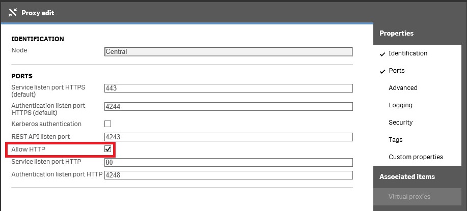
Opening ports on Windows Firewall
Users access to a Qlik Sense server node through 443(HTTPS), 4244(HTTPS Auth), 80(HTTP) and 4248(HTTP Auth). Make sure that these ports are opened on Windows Firewall and users are accessible to Qlik Sense Hub. In this article, ICMP(Ping) is used for server health check by BIG-IP LTM, so ICMPv4 also needs to be allowed on the firewall setting.
BIG-IP LTM VE Setup
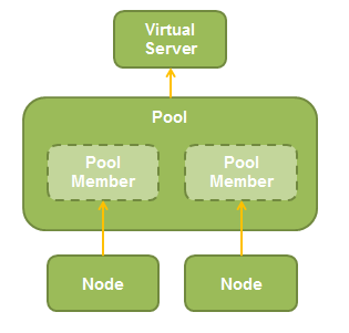
You need to add "Node", "Pool" and "Virtual Server" to setup load balancing on BIG-IP LTM. Users access to a virtual server. The virtual server is associated with a pool, and BIG-IP distribute the user traffic across pool members (=nodes) registered in the pool.
Health monitor checks the health of pool members. You can setup the health monitor on the following three different layers:
- L3: IP address check with Ping (ICMP)
- L4: Service port check (TCP/UDP)
- L7: Application check (ex. HTTP status code)
You can use different monitoring methods for nodes and pools. They are in parent-child relations, so when a node went down, its pool member also goes down, and when all node members in a pool went gown, the pool also goes down. In this article, L3 and L4 health monitoring are used for nodes and pool respectively.
Creating Nodes
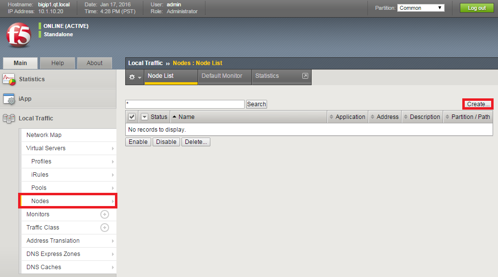
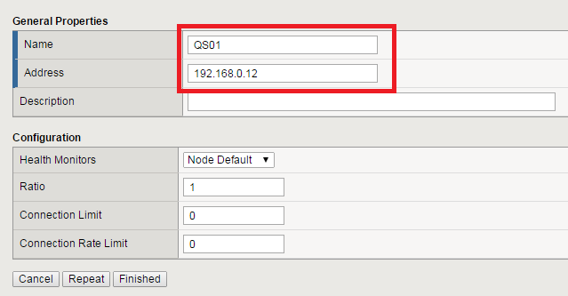
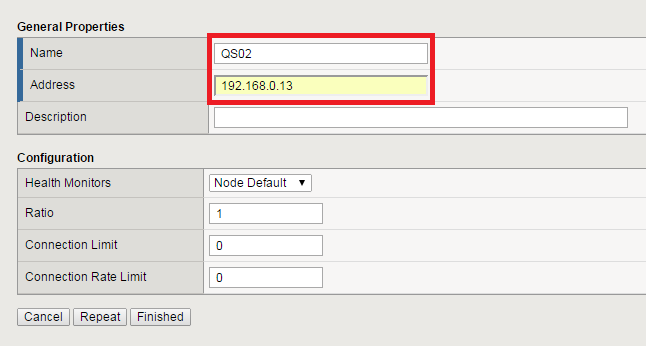
Nodes are associated with (Qlik Sense) servers. Here, we create two nodes (Qlik Sense Server 01 and 02). Also, we specify "icmp" (L3 health monitoring) as a default monitor.
Select "Local Traffic" > "Nodes", and click "Create" button.
Create a node for Qlik Sense Server 01.
Create a node for Qlik Sense Server 02.
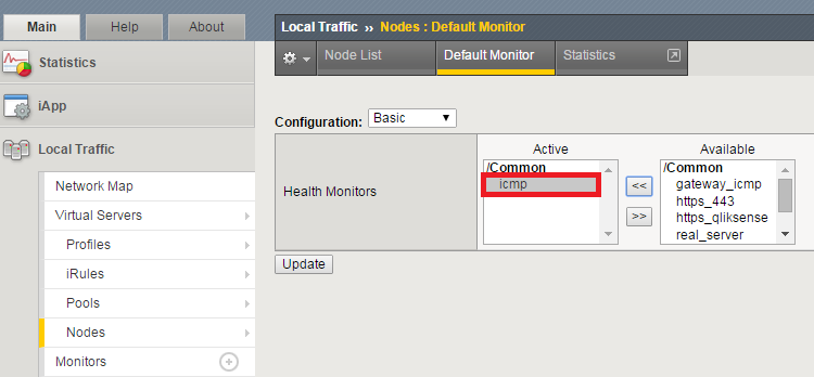
Both QS01 and QS02 are configured to use default health monitor. Now, we select the node default monitor. Select "Local Traffic" > "Nodes", and "Default Monitor" tab. Move "icmp" to active list and click "Update".
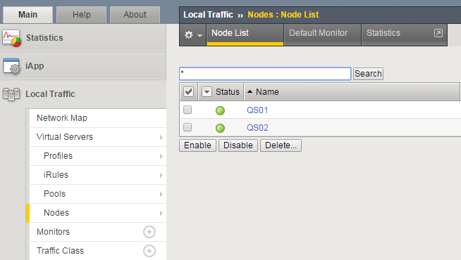
Open "Node List" tab, and make sure that the status of both nodes are active. When the status stays inactive, make sure that the Qlik Sense server nodes are online and ICMPv4 port is opened on Windows Firewall of these nodes.
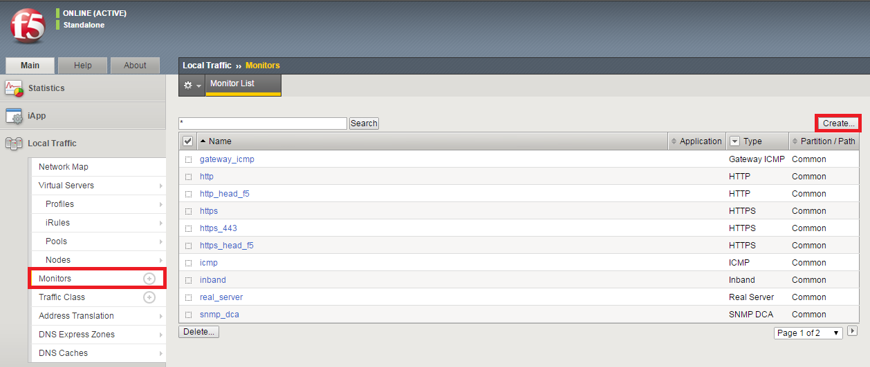
Creating Monitors for Pool Health Checking
For the health check of nodes, we used existing "icmp" monitor in the previous step. Here, we create a tcp(L4) monitor for pool members.
Select "Local Traffic" > "Monitors", and click "Create" button.
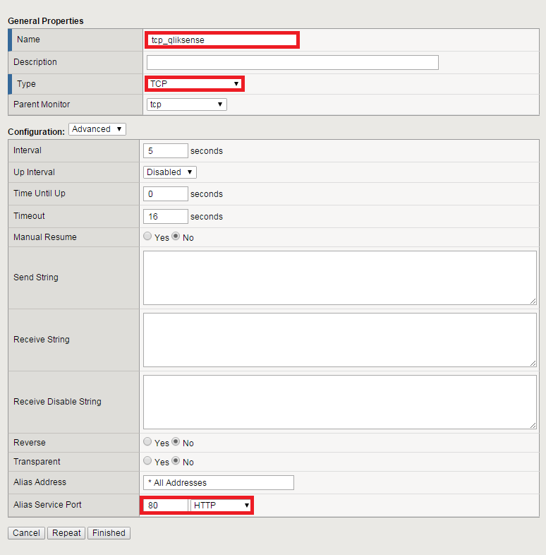
Specify the following settings and click "Finished". (Here, HTTP is used for health check. When you would like to check the health of HTTPS ports, specify "443 HTTPS" for Alias Service Port.
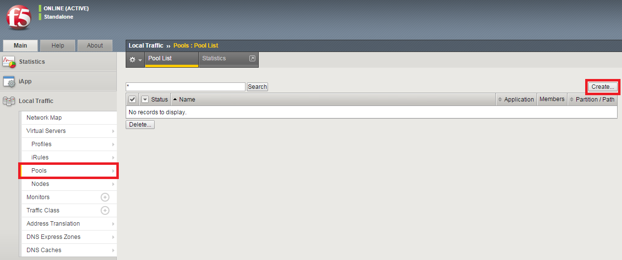
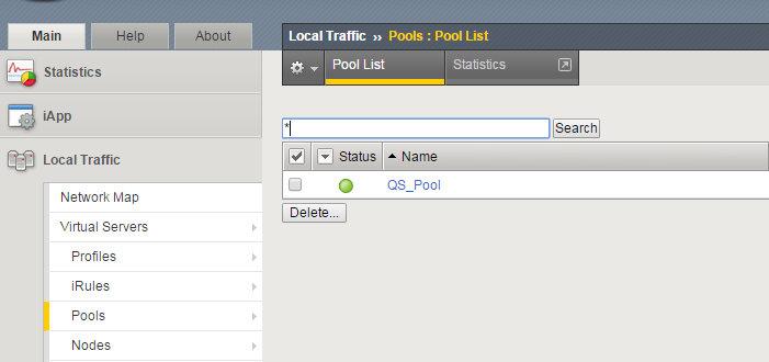
Creating Pool for Grouping Nodes
Multiple nodes can belong to a pool as pool members. The transactions from users are load balanced within the pool members of the pool based on the load balancing method to be specified here.
Select "Local Traffic" > "Pools", and click "Create" button.
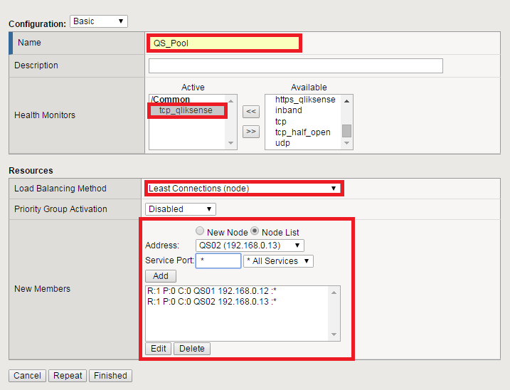
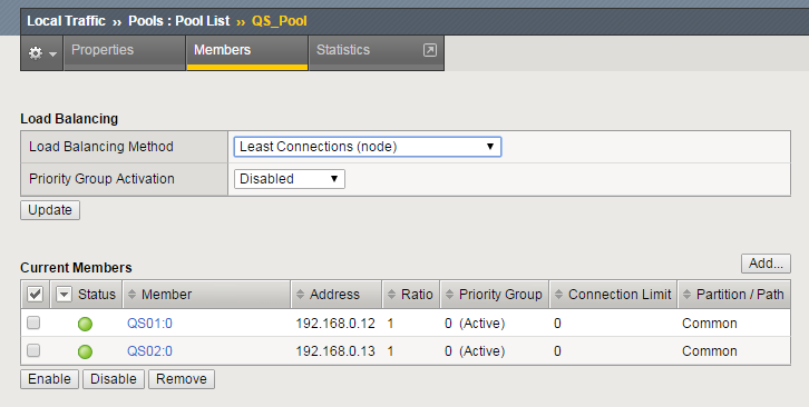
Specify the following settings and click "Finished". Here, we select "tcp_qliksense" for the health monitor, which is created in the previous step. You can also select "Load balancing Methods" among "Round Robin", "Least Connections"..., etc. Here, we select "Least Connections" where a new connection is send to a node with least number of active connections. For "New Members", we select "QS01" and "QS02" with all service ports available.
Open "Pool List" tab, and make sure that the added pool is in active state.
Open "Member" tab, and make sure that the status of both members are active. When status is in inactive state, make sure that port 443(HTTPS), 4244(HTTPS Auth), 80(HTTP) and 4248(HTTP Auth) are opened on Qlik Sense server nodes.
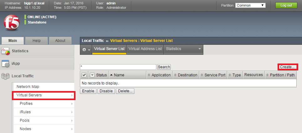
Creating Virtual Server
Virtual servers are represented by virtual address and virtual port, and they are associated with a pool defined in the previous steps. Users on an external network access to virtual server, which then directs the traffic to server nodes associated with the pool/virtual server.
Select "Local Traffic" > "Virtual Servers", and click "Create" button.
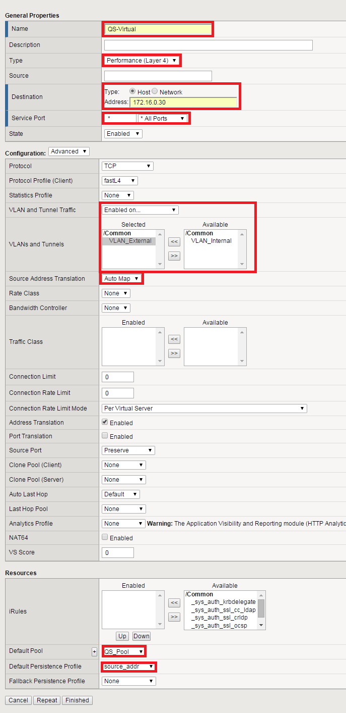
Specify the following settings and click "Finished". We select "Performance (Layer 4)" for "Type". The default setting "Standard" also works, but it makes BIG-IP LTM operate as full proxy which also handles L7. Here, we are going to load balance traffics with L4 switching, so "Performance (Layer 4)" is more effective in term of performance. We input IP address for user access in "Destination". We enable traffic only from the external network in the "VLAN and Tunnel Traffic" setting, and specify "Auto Map" for "Source Address Translation", which translate source IP address on BIG-IP LTM in the similar way as NAT. We associate the virtual server with "QS_Pool" created in the previous step on "Default Pool" setting. Finally, we select "source_addr" (source IP address) for persistence (sticky session). Persistence timeout is defaulted as 180 seconds. Change the setting from "Local Traffic" > "Profiles" > "Persistence" when it is necessary.
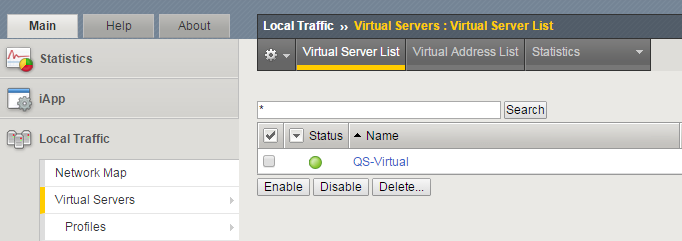
Open "Virtual Serve List" tab, and make sure that the status of the created virtual server is active.
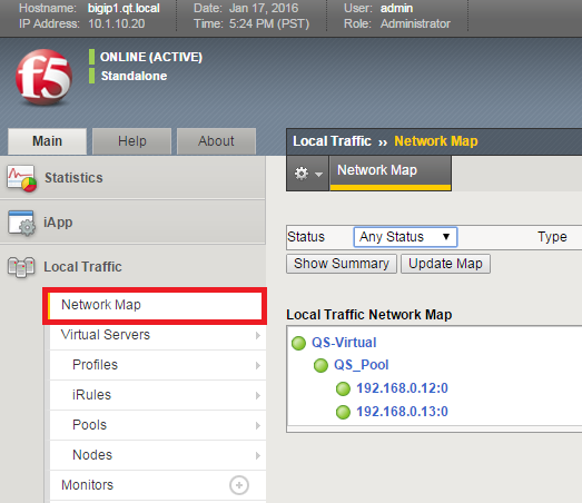
Open "Network Map", and make sure that the status of members in the network map are active status.
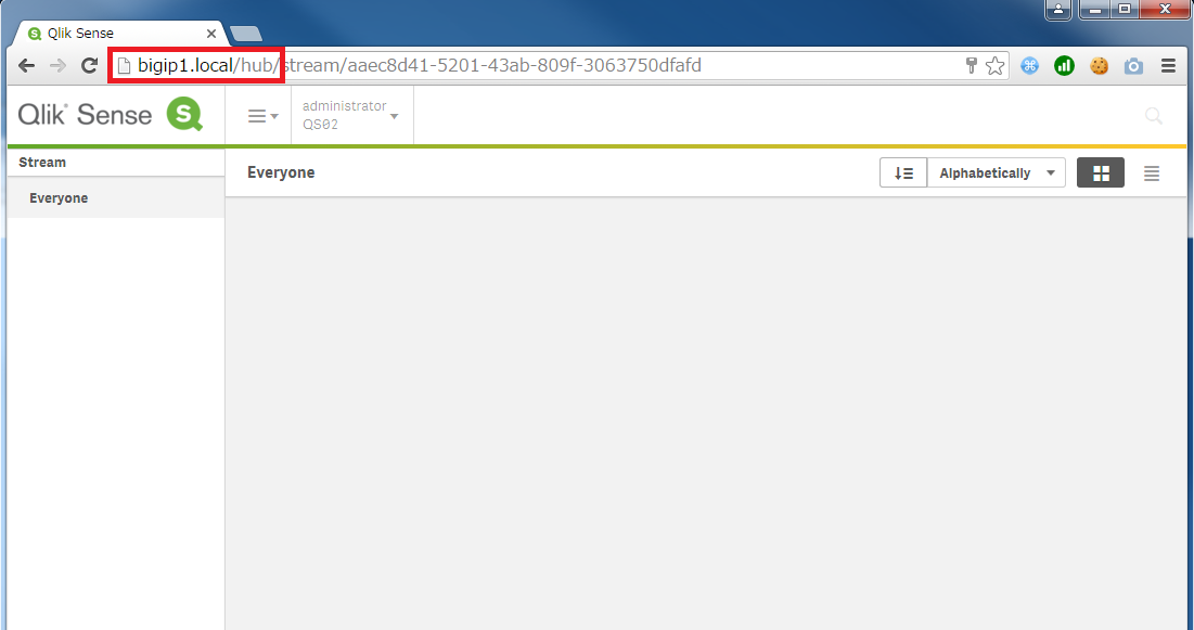
Verifying Access to Qlik Sense
Access to the IP address of the virtual server on BIG-IP LTM and verify that you can connect to Qlik Sense Hub. (The settings above should work both for HTTP and for HTTPS access.)